
In this post we will discuss everything about odometry.
at the end you will be able to answer,
how we can calculate odometry?,
what are the options we have?,
what kind of sensors we can use?
Let’s Start
Odometry means,
in simple term, finding the current position of the robot within working environment.
For that we can have the multiple sensors, mounted on the robot and/or on the floor and remains static throughout.
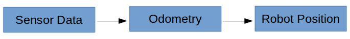
Odometry is a process of converting the sensor data into Robot Position
At this moment we restrict our robot as Planar Mobile Robot, that is for moving on the planar ground, not flying robot like quadcopters. So the robot can have the 2 linear motion in X and Y axis and 1 angular motion (yaw) in Z axis.
For Planar Robot Position Means
- Position in X Direction
- Position in Y Direction
- Current Orientation
For calculating this three Quantities we require sensors that can calculate linear and/or angular measurements reliably.
- Encoders
- IMU
- Laser Distance Sensor
- Stereo Camera
- Beacons
- etc…
If you don’t know about this sensors then
You can learn about them from these links: Encoders IMU Laser Distance Sensor
Now, you have an idea about the sensors.
Using Different combination we can calculate the odometry.
- two parallel Encoders (aka differential drive)
- two perpendicular encoders( for holonomic drive)
- encoders + IMU
- Laser Distance Sensor+ IMU
- Stereo vision camera tracks position
- using the concept of relative position from beacon
and many more…
We will now understand differential wheel drive and implement the navigation in it. Once it gets completed we will learn about Omni Drive too.
Differential drive is also called as Non-holonomic drive. Because it doesn’t have 3 independent Degree of Freedom.
Basically differential wheel robot consists of
- 2 Robot wheels (in some cases, with encoders)
- 1 Castor wheel
- encoder wheels (when motors are not directly coupled with wheels)
- robot chassis
- electronics (controller, motor drivers,..)
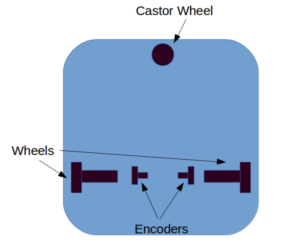
From the above picture you will understand the differential drive very effectively.
There are two configurations as discussed above,
- encoder coupled with motor wheels
- encoder independent of motor wheels (better)
It it always advised to choose encoder independent of motor wheels because of the fact that in many case wheel skids (slips) at the position. So this case the calculated Odometry will be wrong. In the former method, encoder wheels are forced to the ground using springs that ensures skid free motion of encoder wheels.
Let’s understand how we get Odometry values in case of differential wheel drive.
For that we will follow the convention of co-ordinate system.
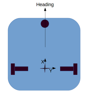
Case1. If the robot moves into X direction then the Encoder values of both the encoder will be same.
new position= old position + (dist_travelled by left+dist_travelled by right)/2
new orientation = old orientation
Case2. If the robot rotates on it’s own axis then the Encoder values of both the encoder will be same but having different directions.
new position = old position
new orientation = old orientation
+ ( distance travelled by left – distance travelled by right) /
distance between the encoder wheels
By combining these two results we can have the kinematic model of the Differential Wheel Drive Robot.
That’s all for this post.
The kinematic model of this robot and the code for calculating odometry we will discuss in the next post.
